This is my second RFLink hardware build. If you missed part 1, check it out here: How to make a $4 RFLink for 433MHz home automation!
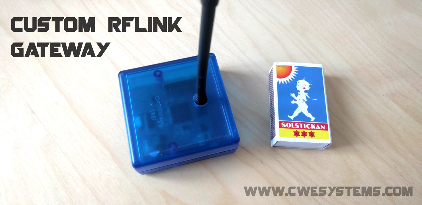
The goal with this project was to build a small and neat RFLink dedicated to only be used as a gateway for 433MHz radios. But with full functionality, which supports the entire firmware.
What is RFLink?
It’s an 433MHz gateway designed to communicate with “standard” wireless -wallplugs, -switches, -weather stations and -temperature sensors. It’s built upon an Arduino (the full project uses an Arduino Mega) and is designed to be controlled by an home automation controller (eg Domoticz or Home Assistant). The receiver and transmitter is within the ISM free license band, is based on ASK-modulation and the protocol is OOK.
Link to the RFlink project. I’m not a developer/creator of the RFLink project, this is just my hardware contribution.
Hardware:
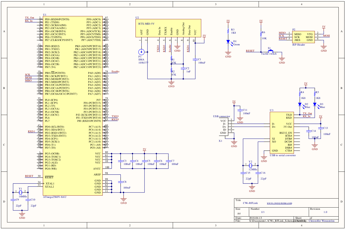
The hardware is based on a ATmega2560, because I wanted to be able to run the full Arduino Mega 2560 firmware. The RF-module is a “RTX MID 5V” from Aurel Wireless, it’s a 433MHz Transceiver. I used a ch340g as a USB to UART converter, beacuse it’s reliable and cheap.
I don’t think the hardware needs any more explanation, here is the schematic:
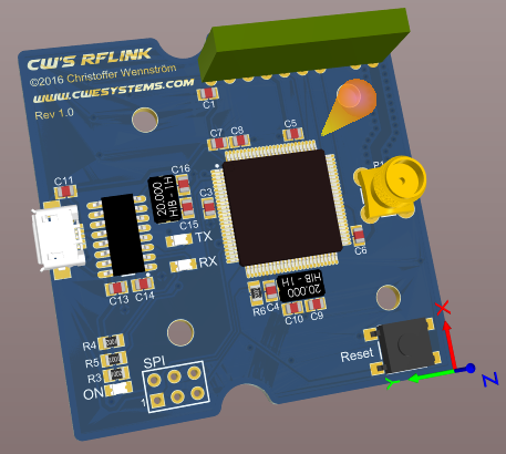
The PCB:
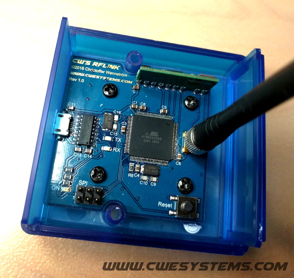
Some pictures of the build:
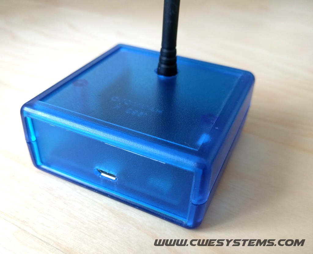
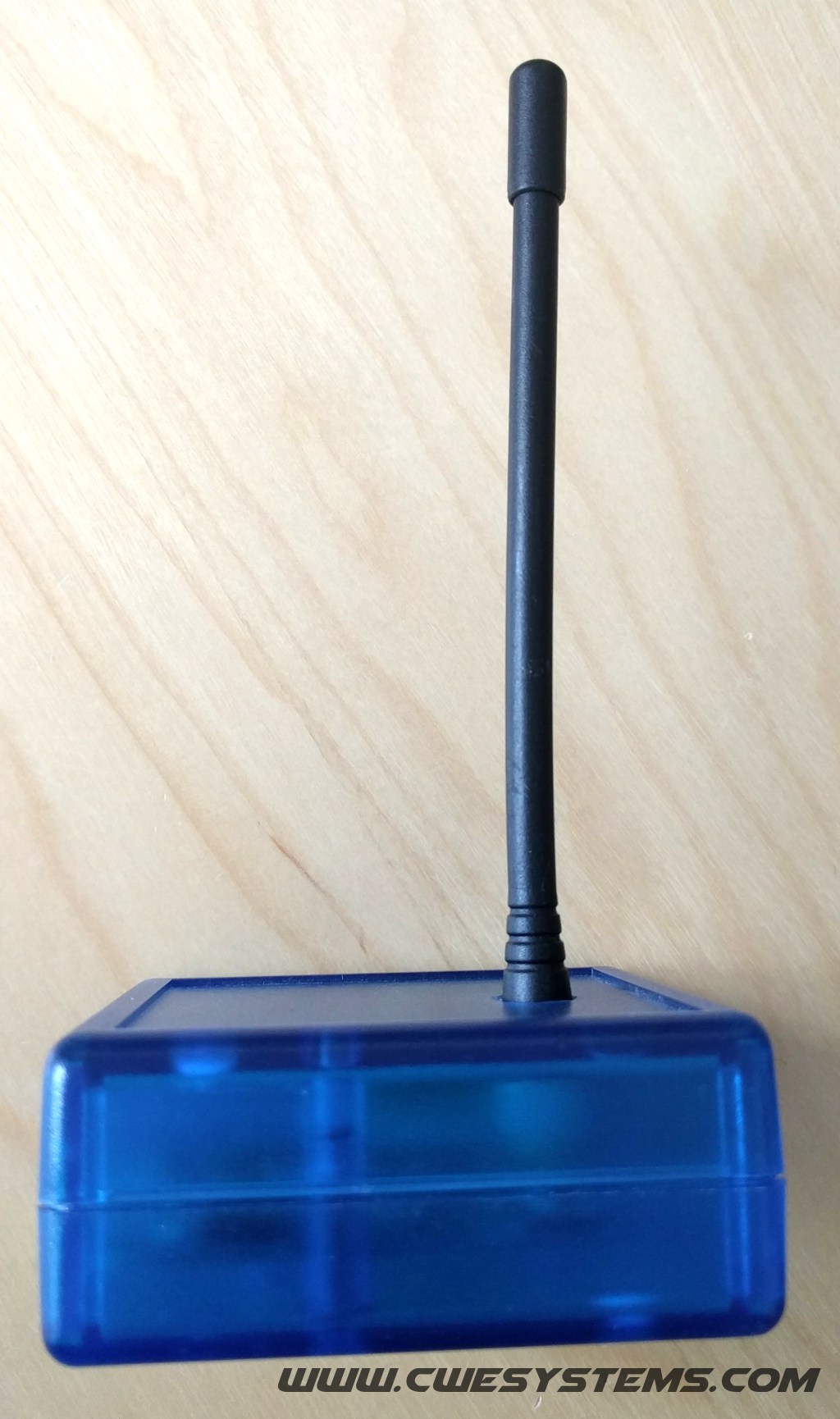
Problems:
I forgot to add a 100nf capacitor between CH340G (DTR) to ATmega (reset). This is the Arduino flash-reset capacitor, which is used to reset the microcontroller and get it into bootloader mode, when you upload firmware to it. But this is no big deal for me, I flashed the ATmega with an external programmer trough the ISP header.
Software/Firmware:
With this you can either use the open source version of RFLink, https://github.com/cwesystems/RFLink or the closed source version, http://www.rflink.nl/blog2/download
Conclusions:
I’m happy with the result, it worked really good! As for now I have build 4 units, all are used 24-7.
But if you want to build one, remember to add a flash-reset capacitor!
Open source:
You can find the schematic, pcb and documents on my github:
Your getway looks very good.
I will try to produce one and will try to modifiy schematic ant PCB to add the missing cap. At works, we are using Altium, I will ask a collegue to do the modification (I am on the software side).
Nice!, yes build one you to, it’s a fun project.
Please send me a picture of your build, it’s always interesting to see 🙂
And share your pcb and schematic so other can take benefit of your cap-fix.
Hello,
very much interested with your project. Unfortunately I do not have access to Altium PCB to export a proper Gerber file.
Would you be in a position to publish gerber files to your github repo? (would be even perfect
with the cap fix added 😉 )
For example here is the detailed settings on how to export from JLCPCB: https://jlcpcb.com/help/article/8-How-to-export-Altium-PCB-to-gerber-files
Thanks
Hello,
Wonderful, I found what I’m looking for but… not sure how to get the hardware since I never done it before.
I was wondering if you fixed the missing cap and if, in any way, I can order one already build ?
If not, how do I order it (and how to can I fix it myself) ?
Hi
The missing cap is only if you are interested to be able to upload firmware with USB cable (serial port), it is to reboot the atmega to bootloader mode.
You can flash the ATMega with a ISP programmer.
Hi.
Did you happen to have one piece of this for sale?
If not, would you do another batch and sell one for me?
I really like the small factor of this. I’m using RFLink right now but Arduino Mega board is a bit large for DIN mounting.
Yes I have one I can sell!
Please contact me if you have one more for sale.
I’d like to buy some too!
Hi
I have 2pcs to sell now, I have sent you an email.
Thanks!
Please contact me if you have one more for sale.
If you have one for sale I would be very interested. I am not savvy enough to fix the cap fix although I would like to learn.