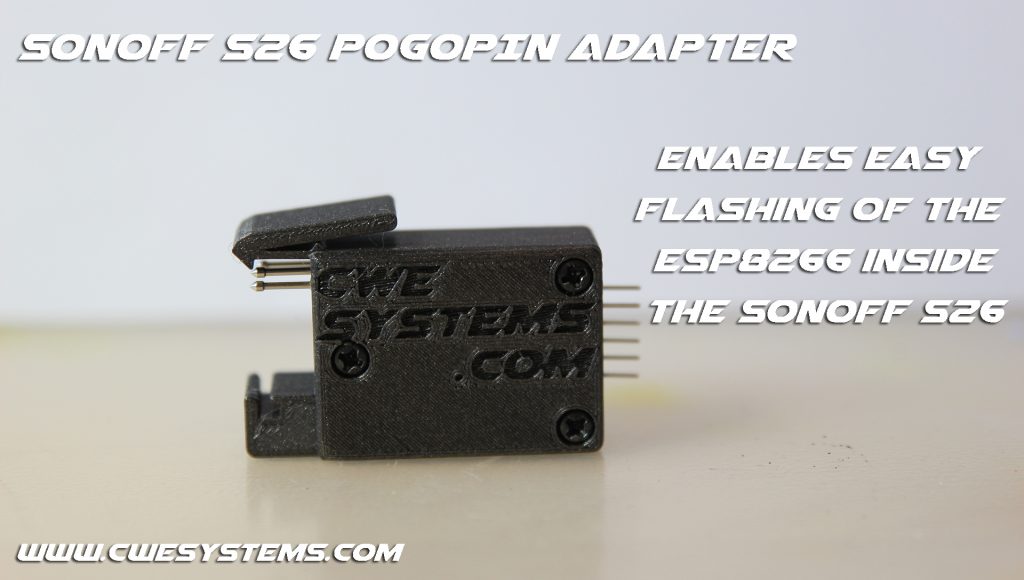
I bought a couple of Sonoff S26 Wifi-plugs. These are built with an ESP8266 wifi chip and can be programmed with custom firmware.
I wanted to flash them with Tasmota firmware and didn’t want to solder wires to every one, so I made a pogo-pin flash adapter 🙂
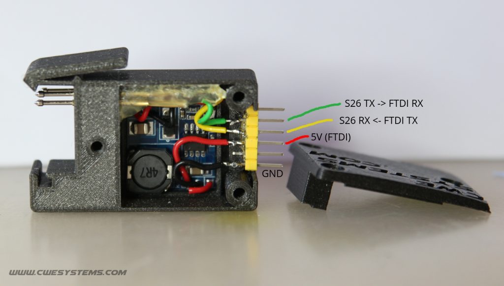
I built it to be used with my FTDI USB to TTL Serial converter. The one I got, have 3.3V pins for communication(RX/TX, etc) and 5V for power. The ESP8266 chip needs 3.3V for both power and GPIO’s so I designed the flash adapter to contain a voltage regulator (FTDI 5V -> Voltage regulator -> 3.3V Sonoff ESP8266).
This features:
- Solderless flashing of Sonoff S26
- Easy to use
- Power ESP from USB
- FTDI USB to 3.3V Serial TTL cable – compatible.
Whats needed:
- 3D-printed parts, STL’s can be downloaded from my Thingiverse.
- Pogo-pins, P100-E2, Diameter: 1.36mm, Length: 33.3mm.
- Voltage regulator, HW-108, 20x20mm.
- FTDI or similar, USB to TTL 3.3V Serial cable.
- Sonoff S26 Wifi plug.
- 3pcs small screws for the top lid.
- 6pin – pin-header.
Disclamer:
- I take no responsibility if you build this or use this!
- Use it at your own risk!
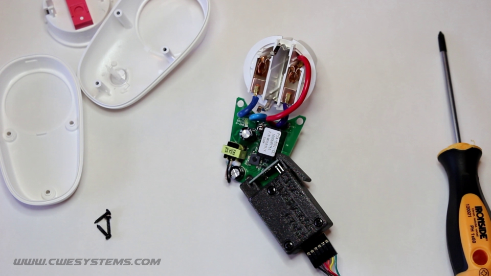
- Never plug the Sonoff S26 in to mains power when you have take it apart!
Build it:
- Print the needed parts.
- Attach pogo-pins.
- Solder wires to voltage regulator. (If you have a USB to TTL serial cable which can supply 3.3V, you can skip the voltage regulator and solder wires for 3.3V and GND directly from pin header to pogo-pins and skip step 4).
- Solder voltage regulator wires (5V and GND (IN) to pin-headers and 3.3V and GND (OUT) to pogo-pins).
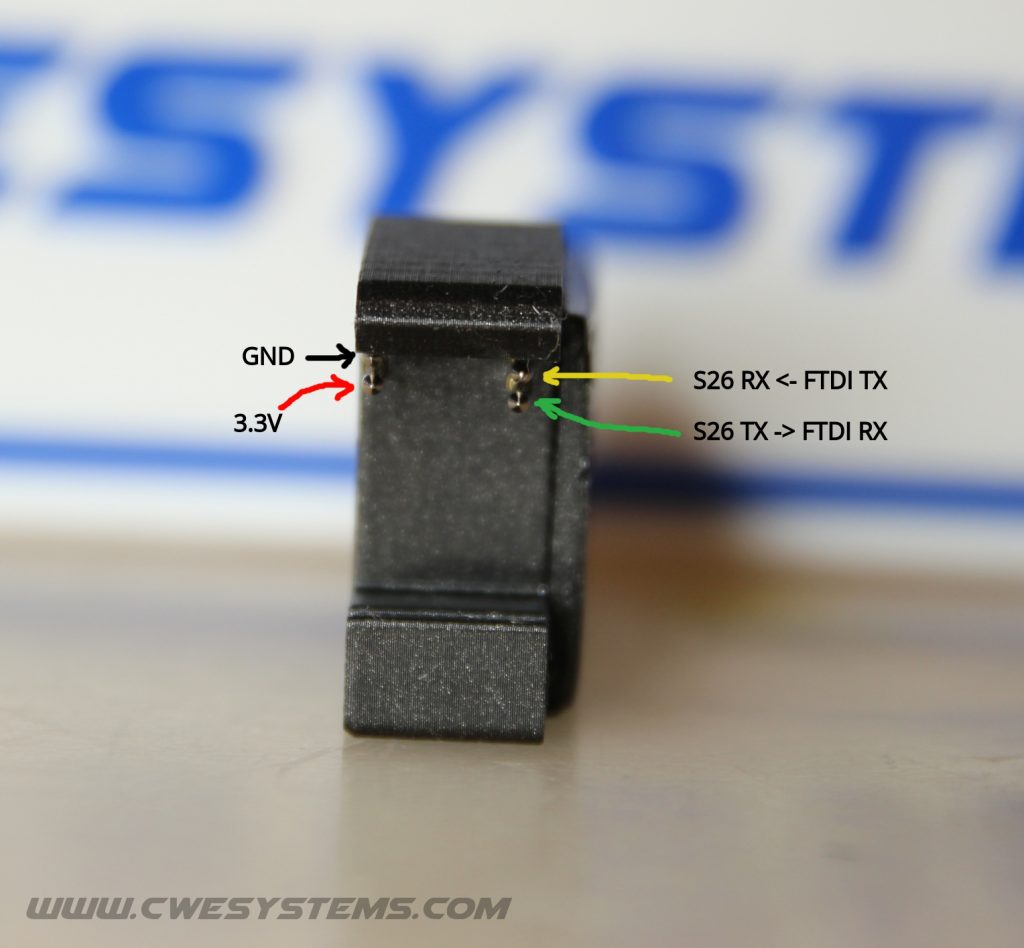
- Solder wires for RX and TX to pogo-pins and pin-header.
- Check all connections and make sure everything is correct.
- Attach FTDI-cable and adjust output voltage from voltage-regulator to 3.3V.
- Use some hot glue to hold pogo-pins and pin-header in place.
- Attach the lid.
- Finished! Time to flash 🙂

How to use the flash adapter: